
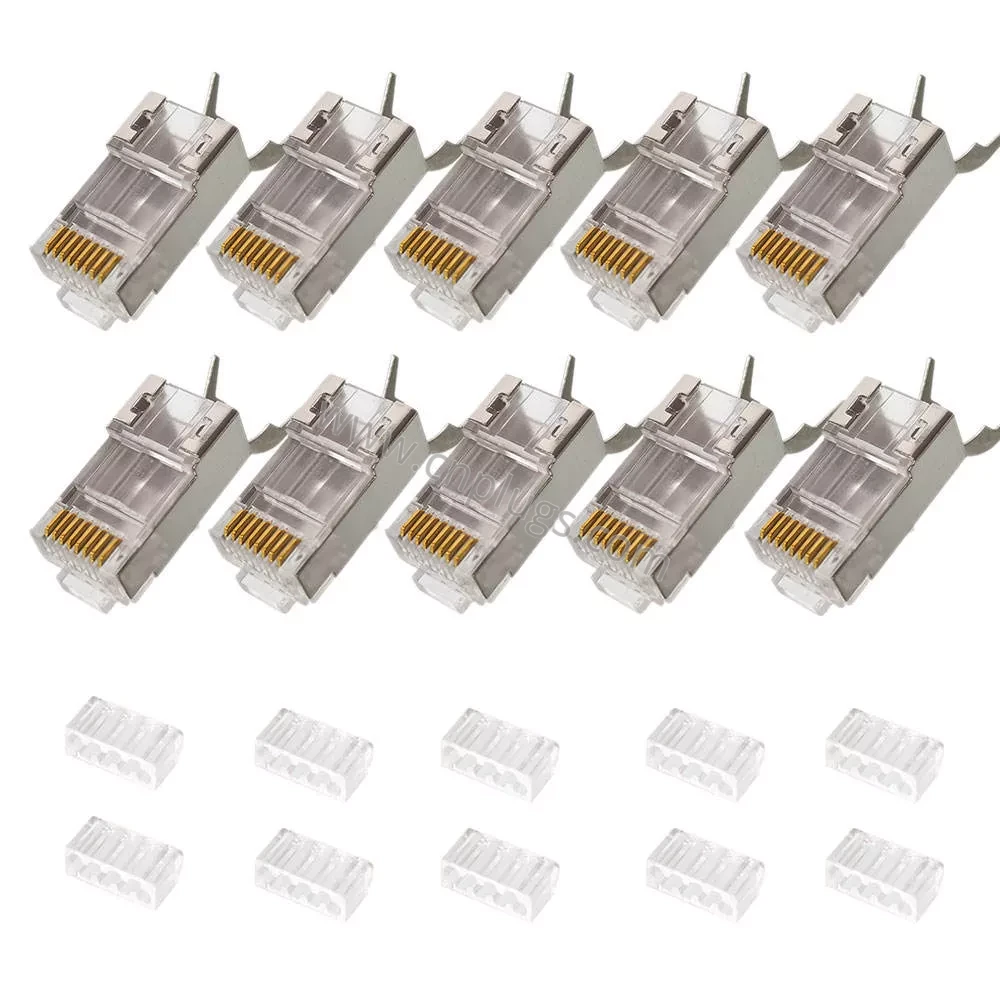
Cat7 Shielded RJ45 Connector Kit with Load Bars: Terminating 10 Gbps Shielded Cable Correctly
Most people who struggle with shielded Cat7 and Cat6A plugs are not doing anything careless. They are using a connector whose load bar does not match their wire, or a crimp tool that cannot close a shield. Both failures look identical from the outside — the cord tests badly, or works today and fails in six months — and neither is fixed by trying harder. This kit is supplied with the numbers you need to check compatibility before you buy, and this page explains the termination properly.
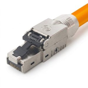
Each kit contains shielded 8P8C crimp plugs and a matching count of 8-hole load bars. Prounta manufactures them for patch-cord plants, data-centre integrators, industrial network builders and distributors who terminate shielded cable in volume and cannot afford a variable yield.
What the Load Bar Does, and Why It Is a Separate Piece
The small clear block supplied with each plug is the load bar, sometimes called a wire separator or insert. Conductors thread through its eight holes before entering the plug body, and it does three things a bare plug cannot.
It fixes the conductor order mechanically, so pairs cannot cross on their way to the contacts. It carries each conductor in its own pocket, which keeps the pairs apart and limits how far the twist has to open up. And it presents all eight conductors to the gold blades in one flat, straight row, so the crimp loads every contact evenly instead of driving hard on the middle four.
That last point is the one installers underestimate. At 10 Gigabit all four pairs transmit simultaneously in both directions, and near-end crosstalk in the last centimetre of the termination sets the noise floor for the whole link. Untwisting more than a few millimetres of a twisted pair undoes the noise cancellation the cable was built to provide. Cat6A and Cat7 tolerate far less untwist than Cat5e — think under 6.5 mm, not 13 mm. The load bar is what makes that achievable by hand.
The Number That Decides Whether This Plug Works for You
Before anything else, measure your cable’s insulated conductor diameter — the outside diameter of one single conductor including its insulation, not the copper and not the jacket.
This kit’s load bar accepts 1.30 mm to 1.45 mm, which corresponds to typical 22–24 AWG shielded Cat7 and Cat6A construction. Outside that window, two predictable things happen. If the conductor is too thin it slides around inside the hole, sits low against the contact blade, and the crimp is unreliable even though the wire physically fits. If it is too thick it simply will not pass through the bar, and forcing it deforms the insulation and changes the pair geometry you were trying to protect.
This is the most common cause of returns in this product category across the whole market, and it is entirely avoidable. It is also why flat or ribbon-style cable cannot be used with a load-bar plug: the geometry is wrong regardless of gauge. If you are ordering in volume, send us the cable datasheet and we will confirm the fit in writing before you commit to a quantity.
Shielding: Where the Earth Path Actually Runs
Cat7 cable is almost always S/FTP or F/FTP — every pair individually foiled, with an overall braid around all four. That construction only performs if the foil and braid are terminated at both ends. A plastic plug leaves them floating, and a floating shield is worse than no shield: an ungrounded conductor running the length of a building behaves as an antenna rather than a screen.
The metal shield body on this plug wraps the connector and closes onto the folded-back foil and braid at the rear, so the earth path is continuous from cable screen, through the plug shell, into the jack shield, and onward to the bonded rack. A screen works only where it is continuous and bonded, and every unbonded end is a hole in it.
The corollary is a rule worth printing on your work instruction. Match the connector to the cable. Shielded plug on unshielded cable achieves nothing — there is no screen to bond. Unshielded plug on shielded cable breaks the path and wastes the cable you paid for. This kit is for shielded cable, full stop.
How to Terminate: The Sequence That Works
1. Boot on first if you are using one. Forgotten constantly, and unrecoverable after the crimp.
2. Strip about 30 mm of jacket without nicking the foil or the conductor insulation. Fold the foil and the drain wire or braid back over the jacket. Do not cut them off. Cutting the braid away is the single most common reason a shielded termination shows perfect wire map and zero shield continuity.
3. Untwist the minimum. Open each pair only as far as needed to reach the bar, then straighten the conductors by pinching them flat between thumb and finger and drawing them through.
4. Thread the load bar in T568A or T568B order and slide it down to roughly 2 mm from the jacket edge. Check the colours now.
5. Trim flush across the front of the bar with a single square cut. Uneven lengths are the reason one contact misses.
6. Insert into the plug with the correct orientation. Hold the plug with the latch facing down and away from you. Wiring the plug upside down is one of the most frequent errors in the field and it produces a cord that looks perfect and works not at all. Push until all eight conductors are visibly seated against the front wall.
7. Crimp with a shielded Cat6A/Cat7 die in one full stroke to the ratchet release, then confirm the rear clamp has closed onto the braid.
8. Test the wire map and the shield continuity — both, not just the wire map. A shield fault is invisible to a basic continuity tester.
Tooling: The Other Half of the Yield Problem
A telephone-style or general-purpose crimper will not do this job. It may close the contacts, and the cord may even pass a wire-map test, but it will not fold and close the shield clamp, so the screen is never bonded. You need an 8P8C ratcheting crimper with a Cat6A/Cat7 shielded die and a shield anvil, driven through a complete stroke every time. Partial strokes are what produce the intermittent cords that fail months later on site.
The crimp itself is a cold-welding process: the contact deforms around the conductor tightly enough to exclude air from the interface, which is what stops oxidation and keeps resistance stable for years. That gas-tight joint only forms at full compression, which is exactly why ratcheting tools exist and why half a squeeze is not half a crimp — it is no crimp at all.
Technical Specifications
| Parameter | Specification |
|---|---|
| Model No. | PR-C7SLB-KIT |
| Product | Cat7 shielded RJ45 8P8C crimp plug kit with load bars |
| Kit Contents | Shielded plugs plus matching count of 8-hole load bars |
| Interface | RJ45 / 8P8C male, cable-mount crimp |
| Category / Class | Cat7 / ISO/IEC 11801 Class F, to 600 MHz |
| Data Rate | 10GBASE-T on a qualified, tested channel |
| Cable Types | S/FTP, F/FTP, STP round Cat7 and Cat6A; back-compatible shielded Cat6 / Cat5e |
| Conductor Size | 22–24 AWG solid and stranded |
| Insulated Conductor OD | 1.30 – 1.45 mm (check before ordering) |
| Cable Jacket OD | 6.5 – 8.2 mm |
| Shielding | Nickel-plated metal shield body with rear foil and braid clamp |
| Housing | Transparent polycarbonate, UL 94V-0 / V-2 |
| Contacts | Three-prong phosphor bronze / brass |
| Plating | 50 µin gold over nickel (3 µin–50 µin available) |
| Wiring | T568A / T568B |
| Tool Required | 8P8C ratchet crimper, Cat6A/Cat7 shielded die with shield anvil |
| PoE | IEEE 802.3af / at / bt, 4PPoE capable |
| Current Rating | 1.5 A per contact |
| Contact Resistance | ≤ 20 mΩ |
| Insulation Resistance | ≥ 1,000 MΩ |
| Dielectric Strength | 1,000 V AC / 1 minute |
| Durability | ≥ 750 mating cycles |
| Operating Temperature | -40 °C to +70 °C (confirm cable jacket rating separately) |
| Compliance | RoHS, REACH, CE, ISO 9001:2015 |
| Packaging | Bulk bag, 50 or 100 pcs jar, OEM carton |
| MOQ / Lead Time | 1,000 pcs; private label from 10,000 pcs; 7–15 days |
What “Cat7” Means on an RJ45 Plug
Worth being straight about this, because it affects what you can promise your own customers. Cat7 is an ISO/IEC 11801 Class F specification rated to 600 MHz. Its native connectors are GG45 and TERA, not 8P8C — and ANSI/TIA never recognised Cat7 at all, going from Cat6A straight to Cat8. So an 8P8C plug, including this one, cannot be a true Class F connector in the strict standards sense.
What it can do, and does, is terminate Cat7 and Cat6A shielded cable into the RJ45 ecosystem everyone actually deploys, delivering reliable 10GBASE-T on a channel that has been tested and passes. That is what buyers searching for a “Cat7 RJ45 connector” genuinely want, and it is worth saying plainly: category performance lives in the cable, the plug geometry and the tested channel — never in the letters printed on the shell. Anyone selling you a “Cat7 plug” that will magically upgrade Cat5e cable is selling you a story.
Who Buys This Kit
Patch-cord factories running shielded 10G lines, where matched plug and bar counts keep the line moving. Data-centre integrators building top-of-rack and leaf-spine jumpers to length. Industrial builders terminating Ethernet beside motor drives and inverters, where the screen is doing real work. Hospital, laboratory and broadcast installers on shielded drops. And distributors stocking a shielded crimp option alongside toolless parts.
If you would rather skip the load bar entirely, our Cat6A and Cat7 shielded pass-through connector lets you thread conductors straight out through the nose and trim flush. If you have no crimp tool on site at all, look at our toolless range in toolless field connectors. The full shielded crimp lineup sits in Cat6A and Cat8 plugs.
Frequently Asked Questions
How do I know if my cable fits before I order?
Measure the insulated conductor OD with calipers — one conductor, insulation included. It must fall between 1.30 and 1.45 mm, and the jacket should be 6.5 to 8.2 mm. If you are unsure, send us the cable datasheet or a sample and we will confirm before you place the order. This one check prevents the large majority of problems with load-bar plugs.
My wires go into the load bar but the crimp keeps failing. What is wrong?
Usually one of three things. The conductor OD is under 1.30 mm so the wire moves inside the bar; the conductors are not trimmed square and flush so one misses its contact; or the crimp tool is not going through a full stroke. Check in that order. If the wire map passes but shield continuity fails, the braid was cut off instead of folded back.
Can I use an ordinary RJ45 crimp tool?
No. You need a ratcheting 8P8C crimper with a Cat6A/Cat7 shielded die and a shield anvil. A standard or telephone-style tool will seat the contacts but leave the shield clamp open, so the screen is never bonded and the cord fails shield continuity while appearing to work.
Do I need the load bar, or can I skip it?
Use it. Without it there is nothing holding pair geometry through the plug, and shop-made cords that skip the bar are the classic cause of return-loss and NEXT failures at 10G. If you want a faster method instead, choose a pass-through plug rather than omitting the separator.
Solid or stranded — do I need two part numbers?
One part number covers both. The three-prong contact seats solid horizontal cable and stranded patch cable in the same die, which is why we specify three-prong rather than two.
Will these work on Cat6A or Cat6 shielded cable?
Yes, provided the conductor and jacket dimensions fall in the ranges above. Cat6A shielded cable is the most common real-world use for this kit. The finished cord performs to the level of the weakest element in the channel, so a Cat6A cable terminated with these plugs gives you a Cat6A channel.
Does it support PoE?
Yes — 802.3af, at and bt including 4PPoE, at 1.5 A per contact. Gold over nickel matters more under PoE load, not less, because a marginal contact interface heats up.
Can we get custom gold thickness, packaging or branding?
Yes. Gold from 3 µin to 50 µin, custom bag and jar counts, your own carton, barcode and logo from 10,000 pieces. We own the moulds and the plating line, so specification changes go straight into production.
What is the MOQ and lead time, and can we test first?
MOQ is 1,000 pieces, 10,000 for private label, with 7–15 day standard lead times. Free samples are available to qualified buyers — send us your cable specification and target volume, and we will ship samples matched to your actual cable rather than a generic pack.
 WeChat ID: