
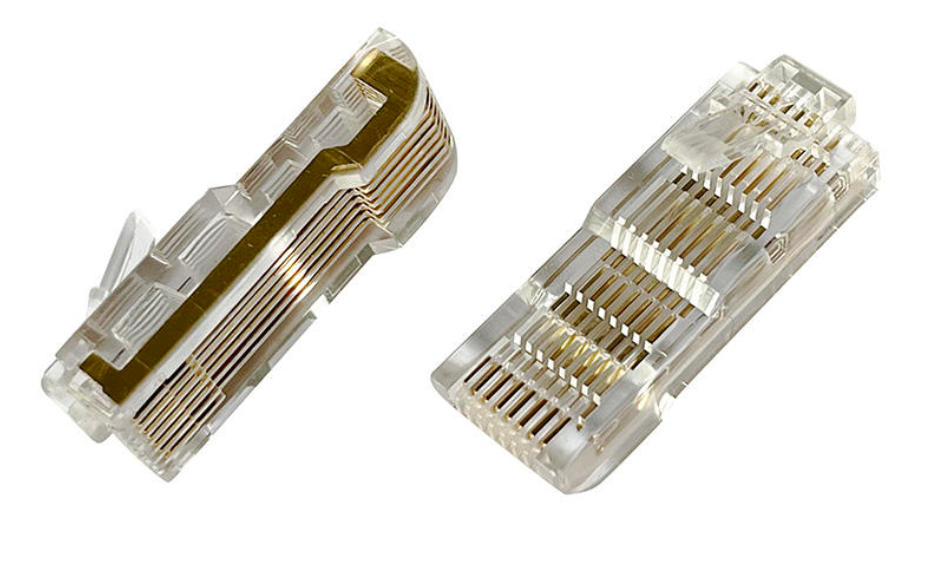
Figure 1: VFD-specific RJ45 8P8C plugs showing the extended parallel gold contact fingers that distinguish them from standard Ethernet crystal heads. The long gold contact array slides into deeply recessed inverter keypad jacks where a normal plug cannot reach.
Introduction: The Two-Dollar Part That Delays Panel Startups
If you have ever stood in front of a VFD panel at 4:30 PM on a Friday, holding a bag of standard RJ45 plugs, trying unsuccessfully to seat a keypad extension cable through a cabinet door and into the drive’s deeply recessed communication jack, you already know the problem. Standard 22 mm 8P8C crystal heads — the same ones used for office Ethernet patch cords — physically will not reach the contacts on most VFD inverter keypad ports. The plug bottoms out on the plastic bezel around the jack before the gold pins make contact, and the keypad either does not power up or drops out intermittently when the cabinet door moves.
It is a frustratingly small issue. The RJ45 plug costs pennies, but the callbacks, troubleshooting hours, and downtime it generates on a single panel build can run into hundreds of dollars. For OEMs wiring inverter harnesses in volume, an incorrectly specified connector is even more expensive: it shows up as field returns, warranty claims, and reputational damage.
This guide is written for the panel builders, MRO electricians, and harness manufacturers who actually specify and terminate these connectors. It explains why VFD keypad ports are dimensionally different from standard Ethernet jacks, why the plugs use extended gold contact fingers rather than conventional end pins, how to choose the right body length (24 mm, 26 mm, or 33 mm), what gold-plating and material specs actually matter, and how pinouts vary across the major drive brands. We also cover installation best practices and common failure modes we have seen during five years of supplying VFD-rated RJ45 connectors to panel shops and drive OEMs.
If you are sourcing connectors for a current project, browse our dedicated industrial and inverter RJ45 plug collection which covers all three body lengths and the 10P10C (RJ50) variant used on certain automation equipment.
1. Why a Standard RJ45 Plug Does Not Fit Most VFD Keypad Ports
To understand why ordinary Ethernet plugs fail on VFDs, look at how drive manufacturers design the operator interface.
On a typical office Ethernet switch, the RJ45 jack sits almost flush with the front panel, and the latch cutout on a standard 22 mm plug clears everything. On a variable frequency drive, however, the communication port is rarely on the surface. It sits:
- Behind a recessed plastic bezel that protects the jack from accidental contact and ESD discharge;
- Inside a deep operator pocket molded into the drive housing, often 8–12 mm below the outer face;
- Behind a removable keypad module, where the jack is only accessible once the keypad is detached, leaving a deep cavity;
- Behind a cabinet door or gland plate, when the keypad is remote-mounted on the door exterior and the cable must pass through a 22 mm panel knockout and still mate on the drive side.
In all of these cases the standard 22 mm plug body is simply too short. But there is a second, more fundamental difference: the contact geometry inside many VFD keypad jacks is not designed for the short, end-facing pins of a standard RJ45 plug.
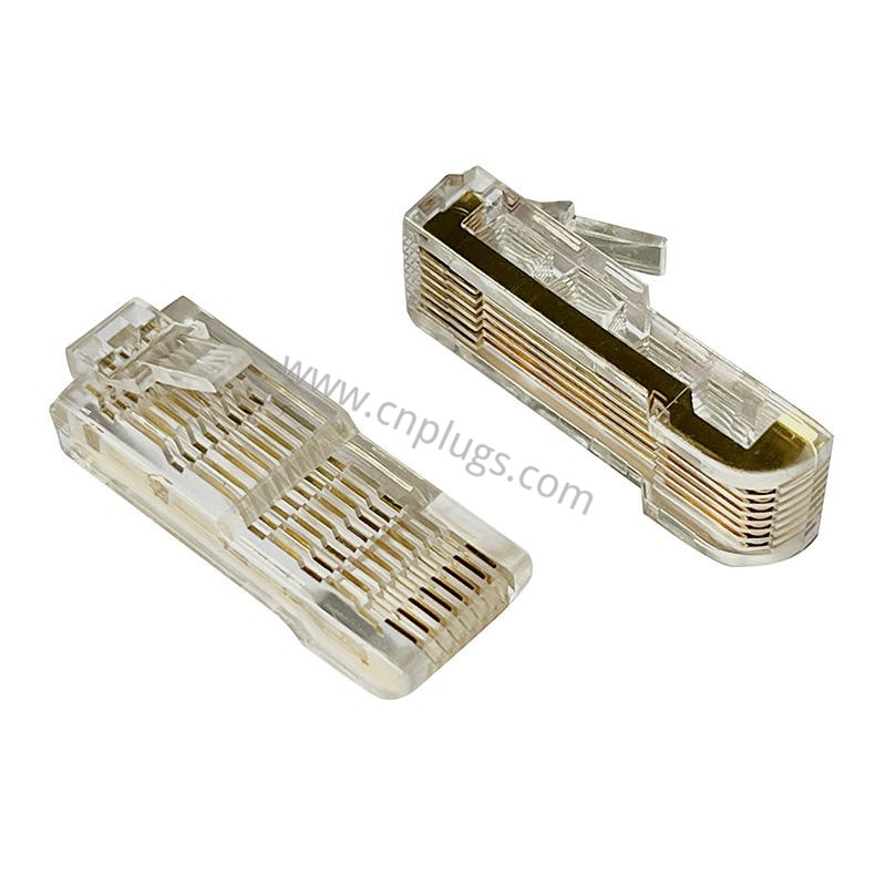
Figure 2: Side-by-side comparison — the VFD-specific plug (right) has an elongated nose with parallel gold contact fingers running along its body, versus the standard crystal head (left) where all eight contacts face only the tip. The extended fingers wipe the jack contacts over a longer insertion depth.
1.1 The Extended Gold Contact Design
If you look closely at a genuine VFD-rated plug (Figure 2), you will notice rows of gold-plated contact fingers running along the top and/or sides of the elongated nose, not just at the tip. This is not a manufacturing defect or a cosmetic feature — it is the key functional difference.
In a standard RJ45 jack, eight short spring contacts are positioned to meet the plug’s pins near the tip. A VFD keypad jack, because of its deep recess and the way many OEMs mold the plastic port, uses contacts that ride along the upper surface of the plug nose as it slides in. The extended gold fingers on the VFD plug provide a continuous wiping surface so that regardless of exactly where the jack contacts land along the insertion depth, a low-resistance gold-to-gold connection is made.
This is why forcing a standard Ethernet plug into a VFD port — even if you somehow get it to latch — usually does not work reliably: the plug simply does not have contact material in the right place to meet the jack’s spring fingers. You may get an intermittent connection when the cable is pressed in one direction, but it will drop out as the plastic creeps or the cable moves.
1.2 Keypad vs. Ethernet: Two Different Electrical Roles
It is also important to understand that these connectors are not always carrying Ethernet. Many VFD keypad ports use the 8P8C physical form factor but carry vendor-specific serial signals — often a UART/TTL or RS-485 link that powers the keypad and carries key/LED data, not IEEE 802.3 Ethernet at all. Some pins carry 5 V or 10 V DC to the remote keypad; others carry bidirectional serial data. The connector looks like an Ethernet plug, but the wiring is often a simple straight-through pin-to-pin cable, and the signaling is nothing like 100BASE-TX.
Confusing these two roles is a common field error: wiring a keypad cable to T568B color code can result in swapped power and ground, or crossed TX/RX, and the keypad will not power up. We cover pinout specifics in Section 5.
2. VFD RJ45 Connector Body Lengths: Which One Do You Need?
The single most important specification on a VFD RJ45 plug is body length — the distance from the very tip of the contact nose to where the cable exits the rear of the plug. Three standard lengths are used across the major drive brands.
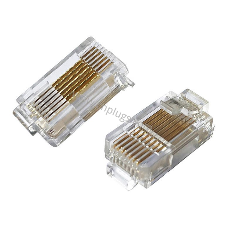
Figure 3: The 24 mm male-to-male (double-ended) RJ45 butt coupler, specified for ABB ACS510 and ACS550 series control panel pass-through connections. Both ends show the extended gold contact fingers.
2.1 The 24 mm Plug — Panel Pass-Through and Butt Coupler
The 24 mm length is used primarily for ABB ACS510 and ACS550 series control panels, where a short male-to-male (plug-to-plug) coupler is required to bridge the keypad cable to the drive’s onboard jack inside the panel. The 24 mm RJ45 male-to-male butt connector for ABB ACS510/ACS550 is specified for this role. It is also used in tight spaces where even a 22 mm plug is marginally too long, such as when a cable must turn sharply right after exiting the plug.
Do not confuse this with a standard RJ45 coupler (female-to-female). The 24 mm VFD part is double-ended male — it plugs into the drive jack on one side and accepts a female-ended keypad cable assembly on the other, functioning as a gender-changer and depth adapter in one compact piece.
2.2 The 26 mm Plug — The Most Common Inverter Operator Panel Size
The 26 mm body length is the workhorse VFD connector. It is specified for the majority of Asian-market drives including many Delta, Inovance, INVT, VEICHI, and older Fuji/Mitsubishi models where the keypad port has a moderate recess of roughly 4–6 mm.
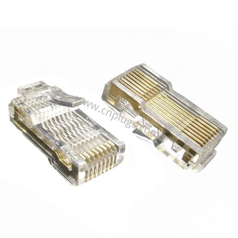
Figure 4: The 26 mm extended VFD RJ45 crystal head — the most widely used size for general-purpose inverter operator panels across Delta, Inovance, INVT, and similar drives.
The 26 mm transparent VFD RJ45 crystal head for inverter operator panels typically ships in 100-piece boxes for OEM harness assembly and MRO stock. It uses standard IDC crimp termination and works with the same 8P8C crimp die used for 22 mm Ethernet plugs, making it a drop-in for production lines.
For general-purpose panel builds where the exact drive model may be substituted during the project lifecycle, the 26 mm plug is a safe middle-of-the-road spec. It is long enough to clear most bezels, but not so long that it protrudes awkwardly on flush-mount jacks.
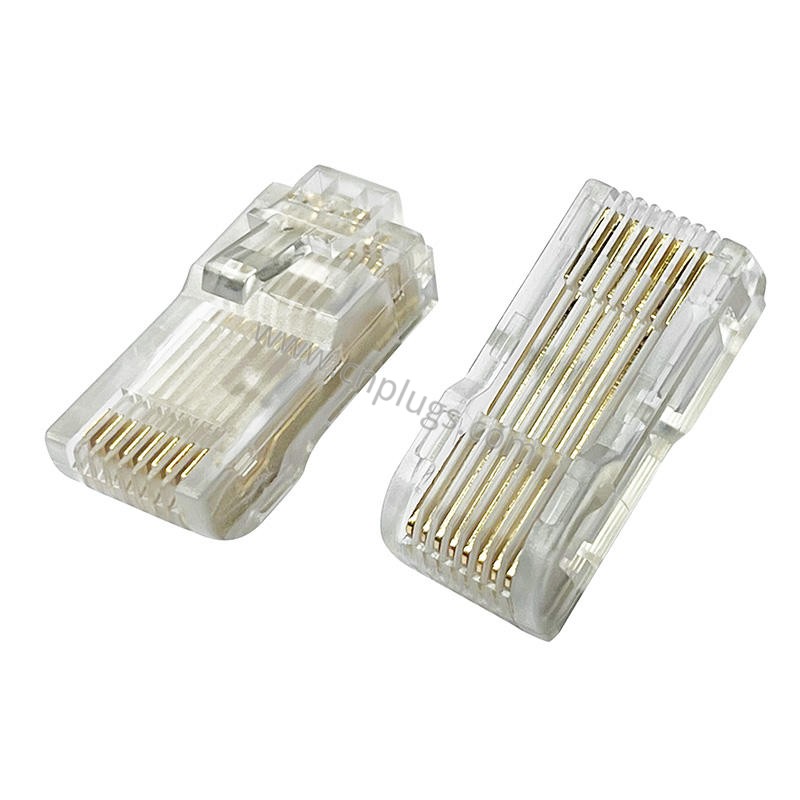
Figure 5: The 26 mm VFD plug in 100-piece bulk packaging for OEM production lines. Consistent dimensional tolerances are critical when thousands of harnesses are being crimped weekly.
2.3 The 33 mm Plug — Deep Recess and Through-Door Applications
At 33 mm, this is the longest commonly available VFD RJ45 body. It is designed for two demanding situations:
- Deeply recessed jacks on larger-frame drives (Mitsubishi FR-A800/FR-F800, Yaskawa A1000/H1000, certain Siemens G120 configurations, and most high-power 75 kW+ drives) where the port sits 10–12 mm behind the front face;
- Through-door keypad extensions, where the cable must pass through a 22 mm (7/8 in.) panel knockout or rubber grommet on the cabinet door and then mate with the drive on the inside — the extra length compensates for the door sheet metal thickness and the grommet depth.
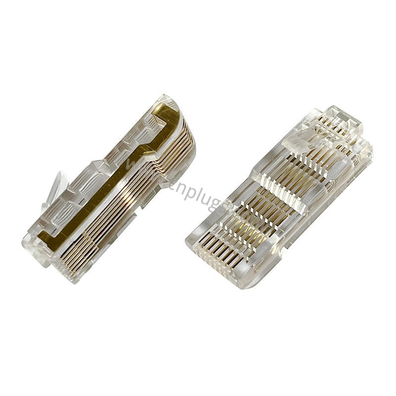
Figure 6: The 33 mm long-nose VFD RJ45 8P8C male plug, showing the long parallel gold contact array. This is the go-to spec for deep-recessed keypad ports and through-door remote keypad mounts.
The 33 mm VFD RJ45 8P8C male plug for inverter keypad and panel communication is the part we most often recommend for field service kits and for OEMs building remote-mount HMI cables. When a panel builder calls us with “my plug won’t reach,” this is almost always the SKU they need.
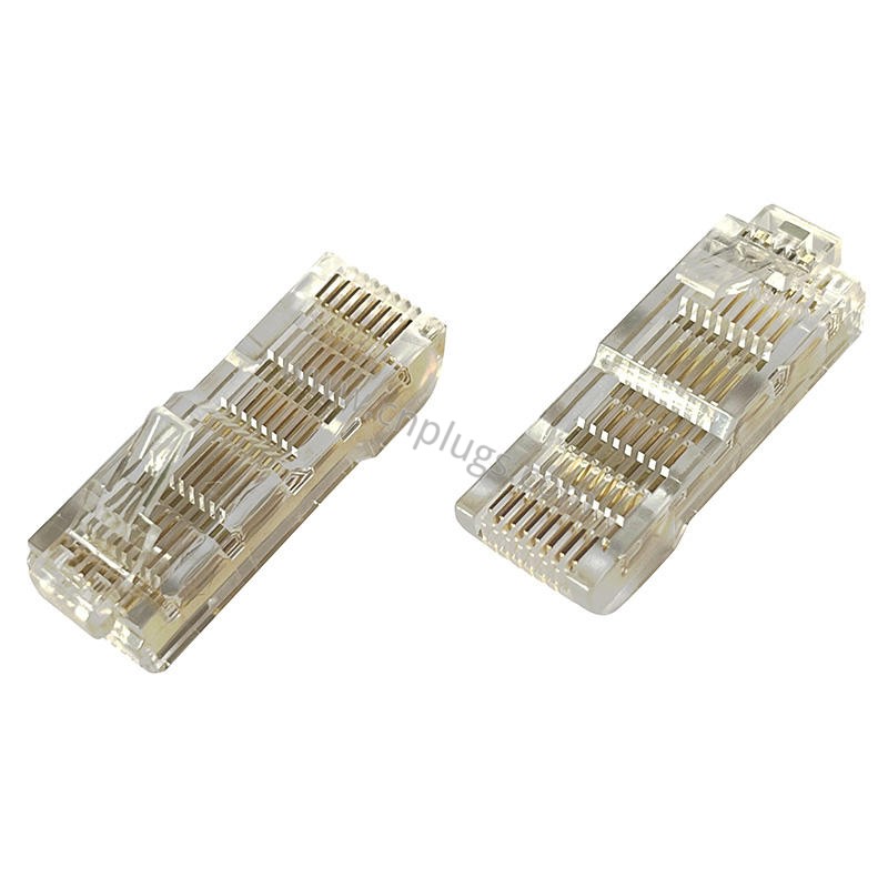
Figure 7: Close-up of the gold-plated contact fingers on a 33 mm VFD plug. The continuous gold surface along the nose ensures a reliable wipe wherever the jack contacts land.
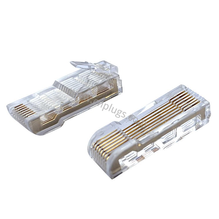
Figure 8: 33 mm VFD plugs in OEM bulk packaging with a keypad cable shown alongside — standard supply format for panel shops and harness makers.
2.4 Quick Selection Table
| Body Length | Primary Application | Typical Drive Families | Termination | Cable Type |
|---|---|---|---|---|
| 22 mm (standard) | Office Ethernet, flush-mounted jacks only | Not recommended for VFD keypad ports | IDC crimp | 24–26 AWG stranded/solid |
| 24 mm (M-M coupler) | ABB ACS510/ACS550 panel pass-through | ABB ACS series | Pre-molded | Mates with female cable |
| 26 mm (extended) | Most inverter operator panels, moderate recess | Delta, Inovance, INVT, Fuji, light Mitsubishi | IDC crimp | 24–26 AWG flat/stranded |
| 33 mm (long-nose) | Deep recess, through-door, remote keypad | Mitsubishi FR-A/F800, Yaskawa A1000/H1000, high-power VFDs | IDC crimp | 24–26 AWG flat/stranded |
| PROFINET metal field plug | Industrial Ethernet field bus, shielded | PROFINET, EtherNet/IP drives | IDC/tool-free | 22–24 AWG STP |
| 10P10C (RJ50) | Proprietary 10-pin automation links | Some PLCs, POS, proprietary inverters | IDC crimp | 24–26 AWG |
When in doubt, measure. A quick reading with a caliper from the front surface of the drive’s plastic bezel to the face of the internal jack will tell you how much added reach you need past a standard 22 mm plug, and you can select the corresponding body length. For panel builders who maintain a field service kit, stocking the 26 mm and 33 mm sizes alongside a bag of 24 mm couplers will cover 95% of the drives you encounter.
3. Material and Plating Specs That Actually Matter in a VFD Environment
VFD cabinets are not office wiring closets. The connector lives next to a high-power switching device that generates heat, vibration, and in some cases airborne oil or corrosive gases. The cheap 100-for-a-dollar crystal heads you find on online marketplaces are built for a two-year consumer product lifecycle. Specifying them on industrial drives causes avoidable failures. Here are the material and plating parameters we recommend evaluating.
3.1 Housing Material — Polycarbonate, Not Cheap Plastic
The transparent housing should be molded from high-strength polycarbonate (PC), ideally UL 94 V-0 flame rated. PC offers the right combination of:
- Dimensional stability across temperature (−40 °C to +85 °C for industrial-rated PC grades);
- Impact and crush resistance during cabinet door closure;
- Transparency to visually verify wire insertion and contact alignment before crimping;
- Resistance to the oils and cleaning agents commonly found in factory environments.
Lower-cost plugs use polystyrene (PS) or ABS blends that become brittle in cold environments and deform when exposed to panel shop temperatures above 60 °C. A cracked housing at the latch base is the most common failure mode we see on returns using non-PC housings. All PROUNTA VFD plugs use imported Japanese polycarbonate for consistent molding quality across production batches.
3.2 Contact Material — Phosphor Bronze with Gold Over Nickel
The extended contact fingers visible in Figures 6 and 7 should be phosphor bronze (not brass) for spring properties and fatigue resistance. Phosphor bronze maintains the specified contact normal force over hundreds of insertion cycles without taking a permanent set — critical on VFD keypads that may be plugged and unplugged during every service visit.
Plating is where the greatest product differentiation exists. The stack should be gold over nickel over copper substrate:
- Nickel underplate (50–100 μ”) acts as a diffusion barrier to prevent copper migration through the gold layer;
- Gold top plate provides a corrosion-free, low-resistance contact surface that does not oxidize, even in humid or sulfur-bearing factory air.
For VFD keypad service, gold thickness is the key purchasing spec:
- Flash gold (< 1 μ”) — suitable only for one-time crimps in consumer products; will degrade within 50 cycles. Do not use in industrial panels.
- 3 μ” gold — acceptable for fixed, rarely unmated connections inside environmentally controlled cabinets;
- 6–15 μ” gold — recommended for VFD panel service; tolerates the occasional keypad swap and field troubleshooting disconnects;
- 30–50 μ” gold — for high-mating-cycle applications (test fixtures, service loaner keypads, frequently reconfigured production lines) and for corrosive environments (chemical plants, coastal installations, welding shops).
We routinely supply 50 μ” gold versions for shipboard and coastal VFD installations where salt spray is a factor, and for OEMs whose field service teams plug and unplug keypads on every maintenance visit. Plating thickness can be specified as a custom option when you contact our engineering team for a quote; every batch ships with a thickness test report on request.
3.3 Latch Design and Retention Force
The plastic latch tab is the most mechanically stressed feature on the plug. Every time a technician pulls on the cable rather than the plug body, the latch takes the load. On VFD panels where cabinets are opened and cables are dressed during service, a weak latch will fatigue and break.
Look for a thick, single-beam latch with a generously radiused root — this distributes bending stress over a larger area and resists fatigue. Avoid plugs with thin, flat latches that are essentially designed to break. The retention force (the force required to pull the plug out of a standard jack) should meet IEC 60603-7 requirements of at least 20 N after 750 mating cycles.
3.4 Load Bar (Wire Separator) Design
Inside the plug, a polycarbonate load bar (also called a wire separator or insert) holds the eight conductors in alignment as they travel from the cable entry to the IDC contacts. Cheaper plugs omit the load bar entirely or mold it as a single flimsy piece; the result is conductors crossing over each other, inconsistent crimp depth, and intermittent connections. A proper load bar with individual channels for each conductor ensures repeatable crimp quality, which is critical when an OEM line is terminating thousands of pieces per week.
4. When VFD Ports Carry Ethernet: PROFINET and Shielded Connectors
So far this guide has focused on the transparent extended-body VFD keypad plug, which is for keypad/HMI serial ports. However, modern VFDs increasingly have a separate Ethernet port for PROFINET, EtherNet/IP, or Modbus TCP communication — and that port requires a different connector.
If a jack on the drive is labeled “PN,” “Ethernet,” “Port 1/Port 2,” or shows the standard Ethernet symbol, it is a true 100 Mbps or 1 Gbps Ethernet port, not a keypad serial port. It will be located on a communication option card or on the drive’s control terminal block, not in the keypad recess. For these ports, the transparent long-nose keypad plug is the wrong part — you need a standard 8P8C Ethernet plug with appropriate shielding.
4.1 Shielded Connectors for VFD-Adjacent Ethernet Cables
Ethernet cables running inside VFD cabinets are exposed to exactly the same EMI that the rest of the panel sees — IGBT switching noise in the 10 kHz to 100 MHz range, magnetic fields from the motor leads, and radiated noise from adjacent contactors and relays. For any cable longer than 1 meter that runs alongside power wiring, use shielded twisted-pair (STP/FTP) cable with a shielded connector that bonds the cable braid to the connector shell 360°.
For PROFINET specifically, the field-installable connector is a two-piece zinc/nickel metal hood with a gold-plated IDC insert and a color-coded wire manager — a completely different construction from the clear keypad plug. Our PROFINET metal field plug kit is the standard field-assembly connector for this application.
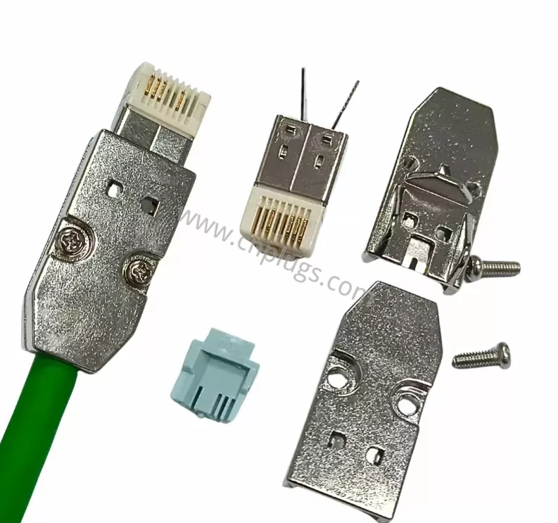
Figure 10: PROFINET field-assembly RJ45 plug kit — two-piece zinc/nickel metal hood, gold-plated IDC contact insert, turquoise PROFINET wire manager, and assembled example on green industrial Ethernet cable. No crimp die is required; a small screwdriver is enough for field termination.
4.2 Cat6A for 1 Gbps Drive Networks
For drives and controllers running EtherNet/IP at 1 Gbps or PROFINET IRT with short cycle times, use Cat6A cable and matching shielded connectors to guarantee bandwidth headroom. The Cat6A STP metal shell modular connector provides 360° shielding and is Fluke DSX-8000 tested to 500 MHz.
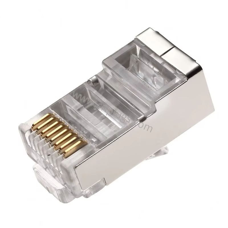
Figure 11: Cat6A STP metal shell RJ45 connector with zinc alloy housing for 10 Gbps industrial Ethernet links in EMI-heavy VFD cabinets. The braided shield bonds 360° to the metal shell for maximum noise rejection.
4.3 Special Pin Counts: 10P10C (RJ50) for Proprietary Systems
A small number of inverter and PLC manufacturers — particularly some older Japanese drives and certain industrial communication gateways — use a 10-position 10-contact (10P10C) connector that is visually similar to RJ45 but wider. A standard 8P8C plug will not fit (it is too narrow), and forcing it damages the jack. For these applications, specify a true 10P10C RJ50 industrial modular plug and use a crimp tool with the correct 10-position die.
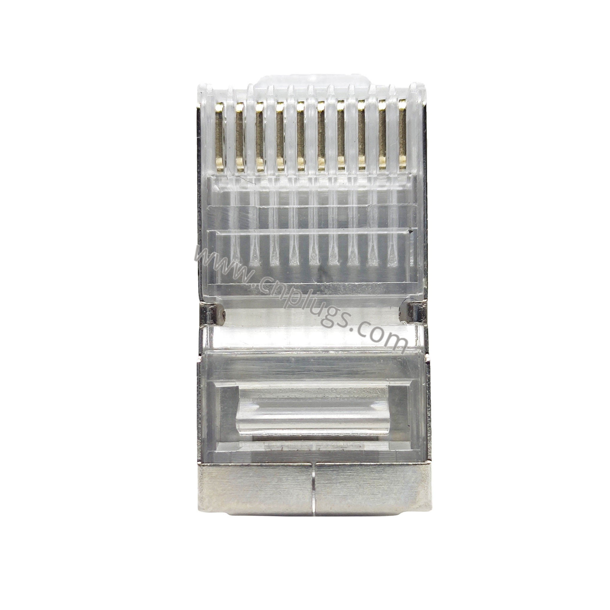
Figure 9: The 10P10C (RJ50) industrial plug — used on certain PLCs, POS systems, and proprietary inverter communication ports. Note the ten contact positions versus the eight on a standard 8P8C plug.
5. Installation Best Practices for Panel Builders and OEMs
Even a correctly specified connector will fail if it is terminated poorly. These are the field installation rules our applications engineers repeat most often.
5.1 Choose the Right Cable
VFD keypad extension cables are almost always flat 8-conductor silver-satin cable (the same physical style as old telephone line cord, but with all eight conductors populated) or 24–26 AWG stranded round cable. Do not use solid-conductor Ethernet cable for keypad cords — solid conductors are designed for punch-down blocks and fixed horizontal wiring, and they fatigue and break after repeated flexing at the panel door hinge. Use stranded conductors for any cable that moves when the cabinet door opens.
For straight Modbus/Ethernet communication between a PLC and the drive’s Ethernet port (as distinct from the keypad port), use a standard Cat5e or Cat6A patch cord with appropriate shielded connectors if the cable runs parallel to VFD power wiring.
5.2 Verify Full Insertion Before Crimping
With transparent PC plugs, look through the housing and confirm that all eight conductors reach the front face of the plug and are visible through the nose. A conductor that stops short of the IDC contacts will make no connection. This is the single most common crimp error, and it is completely avoidable with a visual check.
5.3 Do Not Over-Strip the Jacket
Strip only as much outer jacket as needed to dress the conductors into the load bar — typically 20–25 mm. Any more than that leaves unsupported conductors behind the crimp point, which can short together or pull out under tension.
5.4 Use the Correct Crimp Tool
A 26 mm or 33 mm VFD plug uses the same 8P8C crimp cavity as a standard Ethernet plug, but verify that your crimp tool’s die opening can accept the longer body without interference. Some compact “mini” crimpers designed for pocket tool kits have a shallow die that will not close over a 33 mm plug. A full-size professional RJ45 crimp tool is the right choice for production crimping. Keep the die set clean and replace it after every 10,000 crimps or if you notice inconsistent crimp depth.
5.5 Use a Strain Relief Boot, Especially on Door-Mounted Cables
For cables that pass through a cabinet door and move every time the door opens, add a flexible PVC strain relief boot over the rear of the plug. This prevents the cable from sharply bending right at the plug exit, which is where conductors fatigue-break most often. Color-coded boots (we supply them in black, red, blue, yellow, green, and gray) also help panel builders identify different cable types at a glance — keypad vs. Ethernet vs. serial vs. safety circuit — reducing wiring errors during commissioning.
5.6 Leave a Service Loop
Dress the cable with a gentle 50–75 mm (2–3 in.) service loop inside the cabinet near the drive. This gives technicians room to pull the drive out for service without disconnecting the cable, and it prevents tension from being transmitted directly to the plug when the door swings open.
6. Pinout Considerations Across Major Drive Brands
One of the most common questions we receive is “what is the pinout for a VFD keypad cable?” The answer depends entirely on the manufacturer — and unfortunately there is no industry-standard keypad wiring the way there is for T568B Ethernet. What follows is general guidance; always confirm against the drive’s hardware manual before building cables.
6.1 Straight-Through Pin-to-Pin (Most Common)
The majority of VFD keypad ports use a 1:1 straight-through wiring: pin 1 to pin 1, pin 2 to pin 2, and so on through pin 8. This applies to most Delta VFD-E/CP/MS series, Inovance MD-series, INVT GD-series, and many other drives. A standard straight-through crimp (with conductors loaded in the same order at both ends) works.
Within those eight pins, typical assignments are:
- DC power to the keypad (commonly 5 V or 10 V, often on pin 1 or pin 8);
- Ground (commonly pin 4 or pin 5);
- Serial data transmit and receive (one or two pairs, sometimes half-duplex RS-485);
- Reserved / keypad-detect pins that the drive uses to identify which model keypad is attached.
Crossing power and ground by reversing the cable will not usually damage drives with reverse-polarity protection, but the keypad will not function. Always confirm with a multimeter which pins carry voltage before wiring production harnesses.
6.2 Vendor-Specific Crossover or Remapping
A smaller number of manufacturers use non-straight pinouts on certain models. These cases usually involve:
- Remote keypad cables that cross TX and RX (null-modem style);
- Cables where the keypad connector on one end is physically 8P8C but the pin assignments are mirrored relative to the drive end;
- Drives that use 10P10C (RJ50) connectors instead of 8P8C (see Section 4.3).
For the most reliable results on production harnesses, request a sample keypad cable assembly from the drive manufacturer and verify the pinout with a continuity tester before committing to volume production. We also supply OEM custom-molded cable assemblies with connectors pre-crimped to your specified pinout, which eliminates field wiring errors entirely for high-volume builders.
6.3 Modbus RS-485 vs. Ethernet Over the Same Jack
Some modern VFDs (Siemens G120 with CU250S, Yaskawa GA800, Mitsubishi FR-A800 with Ethernet option card) use the same physical 8P8C jack for both a removable keypad connection and for Modbus TCP/EtherNet/IP/PROFINET communication. In these cases:
- If a keypad is plugged in, it uses the serial/power pinout;
- If an Ethernet cable is plugged in, it uses standard T568B Ethernet signaling;
- The jack auto-detects what is connected, or the function is selected by parameter.
If a jack is labeled “Ethernet” or “PN,” it is an Ethernet port — use Ethernet cable and standard wiring practices with shielded connectors. If it is labeled “Keypad,” “Panel,” or “Operator,” verify the pinout in the manual before assuming Ethernet.
7. Common Failure Modes and Troubleshooting
When a VFD keypad or communication link is intermittent, the RJ45 connection is one of the first things to inspect. These are the failure modes we see most often in returned units and field reports.
7.1 Intermittent Keypad Blank or Reset
Symptom: keypad powers on but randomly goes blank or resets, especially when the cabinet door is moved or when technicians work near the drive.
Likely causes, in order of frequency:
- Wrong-length plug not fully seated — the most common root cause. Upgrade to the 33 mm long-nose plug so the contacts wipe fully.
- Standard Ethernet plug used instead of extended-contact VFD plug — no gold material where the jack contacts ride. Replace with a VFD-specific part.
- Conductors not fully inserted to the front face of the plug (re-crimp with visual verification).
- Broken conductor at the plug exit from repeated flex (add strain relief boot and service loop; re-terminate with stranded cable).
- Worn gold contacts from high mating cycles with flash-gold plugs (upgrade to 15 μ” or 50 μ” gold).
7.2 CRC or Frame Errors on Ethernet Communication
Symptom: drive Ethernet port shows link but logs CRC errors, Modbus TCP timeouts, or dropped PROFINET cyclic data.
Likely causes:
- Split pairs or excessive untwist at the connector (re-terminate with proper pair geometry per T568B);
- UTP cable run parallel to VFD power leads without adequate separation (re-route with minimum 20 cm separation or switch to STP cable with shielded metal-hood connectors);
- Worn contacts causing elevated contact resistance on one or more pins (re-terminate with industrial-rated plugs);
- Solid-conductor cable used at a door hinge with broken conductor from flex fatigue (replace with stranded patch cord).
7.3 No Connection At All After Initial Crimp
Symptom: keypad does not power up at all; link LED does not illuminate.
Likely causes:
- Wrong plug type or body length (see Section 2);
- Pinout mismatch (T568B on one end and vendor-serial on the other);
- Conductors not fully seated past the IDC contacts (re-crimp after visual inspection);
- Crimp tool out of calibration with worn die (replace the crimp tool or die set);
- 10P10C jack mistaken for 8P8C (check the port width carefully; see Section 4.3).
For OEMs who want to eliminate crimp quality as a variable entirely, we offer custom molded VFD keypad cable assemblies terminated and 100% continuity-tested at the factory, available with private-label packaging for your brand.
For OEM customers and distributors, we offer tiered pricing starting at 5,000 pieces for standard VFD plugs, with flexible MOQ for custom-length or custom-molded SKUs. Packaging can be customized from bulk 1,000-piece cartons to branded blister packs — see our OEM/ODM customization capabilities for details on logo printing, housing colors, and private-label cartons.
Conclusion
The VFD keypad RJ45 plug is a small part that causes outsized problems when specified incorrectly. The core takeaways for any panel builder, MRO electrician, or harness manufacturer are:
- Use VFD-specific extended-contact plugs, not standard Ethernet crystal heads. The long gold contact fingers on VFD plugs are designed to wipe the jack contacts over the full insertion depth of recessed ports; a standard plug lacks contact material in the right places.
- Match the body length to the recess depth — 24 mm (for ABB pass-through couplers), 26 mm (general-purpose operator panels), or 33 mm (deep recess and through-door applications). When in doubt, the 33 mm long-nose plug solves more reach problems than any other single SKU.
- Specify industrial materials: polycarbonate housing (UL 94 V-0), phosphor bronze contacts, gold over nickel plating at 6–15 μ” minimum for standard service, 30–50 μ” for high-cycle or corrosive environments.
- Use shielded metal connectors for Ethernet ports (PROFINET, EtherNet/IP) running alongside VFD power wiring; do not use the clear keypad plug on Ethernet ports.
- Verify the pinout against the drive manual. Many VFD keypad ports use the 8P8C form factor but are not Ethernet; do not assume T568B.
- Terminate correctly — full conductor insertion, a load bar, proper crimp tool calibration, a strain relief boot, and a service loop for door-mounted cables.
- Buy from a specialized RJ45 manufacturer that can supply consistent quality across production batches, provide plating thickness and contact resistance test reports, and support custom requirements.
If you are sourcing VFD connectors for an upcoming project or would like to qualify a second-source supplier for current production, we invite you to browse our full industrial and inverter plug catalog or request free samples directly from our engineering team. We manufacture all VFD connectors in our Dongguan facility with in-house mold design, high-speed stamping, controlled plating, and automated assembly — every production lot is tested for contact resistance, mechanical retention, and dimensional compliance before shipment.
 WeChat ID: