
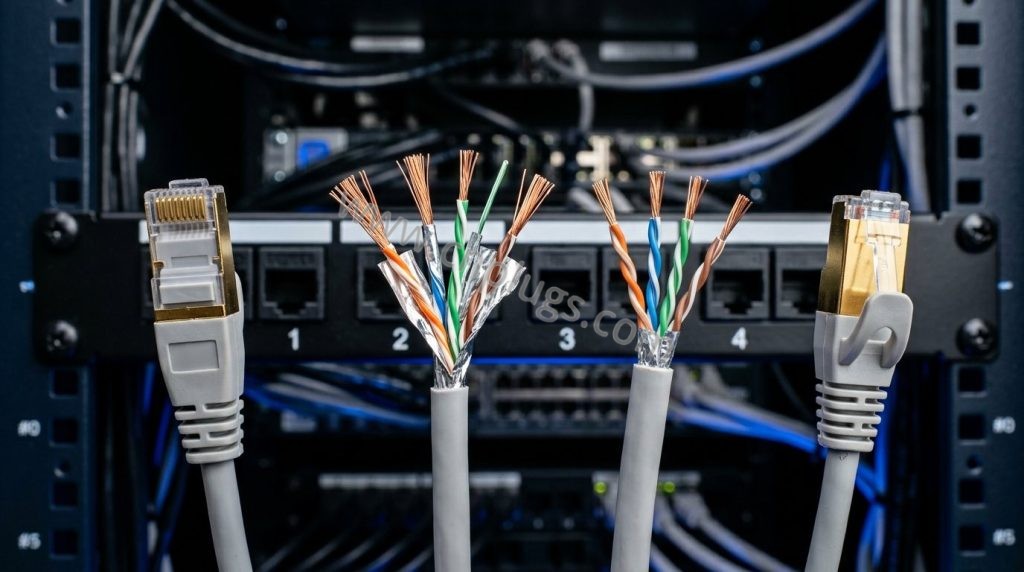
Why a certified permanent link still fails at the switch: the five meters nobody tests, and the six checks that settle it
An RJ45 patch cord is not a short cable. It is two mated connections plus a short cable, and it is normally the only component in the channel that nobody measured. The permanent-link test exists precisely to exclude it. That single fact explains most of the “the wall passed, the port is broken” tickets: the object carrying the signal at both ends is thinner than the cable it joins, made of stranded wire, bent a hundred times a year, and bought on a price per unit rather than a spec sheet. This page runs the arithmetic on it — resistance, heat, return loss, wear — and lists the checks that need nothing beyond a four-wire meter, a caliper, a scale and the tester already in the van.
Quick answer
- The structural reason cords get away with itA permanent-link test measures the fixed plant and leaves the cords out; a channel test includes them. If the handover file is a permanent-link file, the two connections at each end that actually carry the traffic were never in the measurement path. A link can be certified and still have no measured cord at all.
- The number that matters most, and nobody quotesDC loop resistance. A 5 m, 28 AWG cord is 2.13 Ω; a 90 m, 23 AWG horizontal run is 12.0 Ω. Those three meters of jacket at each end add roughly a sixth of the fixed plant’s resistance, and cords are where PoE current is squeezed through the least copper in the least airflow.
- Where a short cord genuinely failsNot attenuation — at one meter there is nothing to attenuate. Return loss and the mated interface: the impedance discontinuity at the plug, the untwisted tail behind the IDC, and an insulation diameter that does not match the plug window. Short cords are harder to pass, not easier, because the cord’s own loss no longer masks the reflections.
- The five-minute test that settles argumentsMeasure one assembly twice: once as a channel with the cords in place, once as MPTL or permanent link with the same cords removed. The difference is the cord. Everything else on this page is a way of predicting that difference before you need it.
- What to stop doingStop treating a category marking on a cord as a measurement. A cord’s category label is a component claim made by its assembler at a stated frequency and length; it says nothing about your plug, your panel, your bend radius or your PoE class.
Sections 3 and 4 are arithmetic you can rerun for your own gauge and length. Section 10 is how to read a cord data sheet. Section 11 is what to do on a receiving bay with four instruments.
- An RJ45 patch cord is two connections plus a cable
- What is inside the jacket, and why it is not reel stock
- The arithmetic nobody runs on five meters
- Heat and voltage drop in the patch field
- Return loss, untwist and the mated interface
- Length budgets, category mixing and the connector count
- Six assumptions about cords that do not survive arithmetic
- Flat and slim cords: what the geometry buys and costs
- Boots, snagless tabs, dressing and wear
- How to read a cord data sheet
- Six checks at the dock
- Triage: symptom → is it the cord? → the one measurement
- What to do with this
- FAQ
- Sources and standards referenced
1. An RJ45 patch cord is two connections plus a cable
Every patch cord adds two mated interfaces to a link: its plug against the panel jack at one end, its plug against the equipment jack at the other. The cable between them is usually the least troublesome part of the assembly. A 3 m cord is not 3 % of a 100 m link that happens to be floppy; it is four connections plus 3 m, in a channel whose total connection budget is counted in the standards and is small.
Three consequences follow, and they explain most of what goes wrong in the field:
- The test configuration decides what gets blamed. A permanent-link test measures the fixed plant between two outlets. It exists so installers can be graded on work they cannot control — not because the excluded parts do not matter. When a link passes permanent link and then misbehaves in service, the difference between those two measurements is made of cords and equipment ports, and the cords are the part anyone can still change.
- The cord is the only component assembled twice per end. Horizontal cable is terminated once, tested once, then left alone for twenty years. A cord is terminated or molded, plugged in, unplugged for a change, plugged into a different port, coiled, dressed, and unplugged again. Each of those actions is a mating cycle on contacts and a bending cycle on the boot — see section 9, where the same arithmetic a customer service desk needs is done in one table.
- Its performance is a claim about an assembly, not a property of a length. Component limits for cords are specified with a stated length, shield construction and category. Cut the length in half and you have changed the object the limits were written for: the loss falls, the reflections do not, and at some lengths the reflection is all that is left. That is not pedantry — it is why a 0.3 m cord can fail a spec a 3 m cord of the same build passes.
The one-sentence version of this article: the cord is the shortest, thinnest, most-mated and least-measured object in the channel, and its two connectors are worth more to link performance than its copper is. Specifying and testing it as “cable, but short” is the error everything else on this page is designed to prevent.
2. What is inside the jacket, and why it is not reel stock
Patch-cord construction differs from horizontal cable in five ways, and each one has a failure mode attached. The vocabulary is worth having straight, because a cord quoted as “Cat6, 28 AWG, molded, PVC” tells you about three of these five and nothing about the other two.
| Variable | What the options are | What it decides in service |
|---|---|---|
| Conductor form | Solid single wire; stranded (typically 7 strands); high-flex stranded (up to 36 fine strands) | Flex life at the boot, and DC resistance. Stranding costs a few percent extra resistance because each strand follows a helix through the conductor — measurable, not assumed. Solid in a cord that is unplugged weekly work-hardens and breaks inside the boot, usually near the point where the jacket ends. |
| Conductor size | 24, 26, 28 and 30 AWG are all sold as patch cords | Everything in sections 3 and 4. Between 24 and 28 AWG the cross-sectional area halves — 0.205 mm² against 0.081 mm² — so resistance roughly doubles for the same length. |
| Screen construction | Unscreened pairs; overall foil (F/UTP); overall braid (S/UTP); pair-wise foil with or without an overall screen (U/FTP, F/FTP, S/FTP) | Whether the screen is continuous into the plug shell at both ends. A screened cord whose plug does not capture the drain wire or terminate the foil is an unscreened cord with extra steps — the same point the shielded-plug article makes about plugs, applied one meter closer to the customer. |
| Jacket compound and rating | PVC; LSZH; plenum-rated; 60 °C, 75 °C or 90 °C temperature rating | Bend behavior in cold weather, whether the boot holds round, and whether the jacket survives being warm for years. PoE makes the temperature rating a data parameter as well as a safety one; see the heat arithmetic in section 4. |
| Termination method | Molded (overmolded) factory assembly; crimped then boot-fitted; field-terminated by the installer | Who controls the untwisted tail behind the contacts (section 5), whether strain relief grips the jacket or the conductors, and whether the build can be inspected at all. Molding is a trade, not a guarantee — it hides the work it protects. |
2.1 The question that comes up on every job: can cords be made from the reel?
Yes, and the result is a permanent cord rather than a patch cord. Reel stock is solid conductor, sized for the fixed plant (usually 22–24 AWG), with a jacket and insulation geometry chosen for a termination that is never moved. Terminate it in a plug and you get three properties at once: lower resistance than any stranded cord of the same length, because solid is the shortest path through the copper; a jacket too stiff for a small boot to control, so the bending force lands on the termination instead of the cable; and a conductor that fatigues where it flexes, because solid copper tolerates far fewer bending cycles before it cracks than a bundle of fine strands does.
The practical reading: reel-stock cords in an equipment room that is repatched twice a decade are common, cheap and electrically excellent. The same assemblies taped to a door frame or routed under a raised floor that gets walked on are the ones that come back as “intermittent”. The plug’s side of that argument — the window that has to grip the insulation and the jacket that has to sit inside the boot — is covered in the retention article; the point here is that a cord’s construction has to satisfy both sides at once, and a cord made from horizontal cable is optimized for neither.
2.2 What molding does and does not buy
An overmolded boot bonds the plug to a meter of jacket, so a pull loads the jacket rather than the contacts. That is a genuine advantage, and it is the whole advantage. What molding cannot do is make an undersized conductor, a bad untwist or a mismatched insulation diameter acceptable — it can only make them invisible, which is why a molded assembly with no published per-pair resistance figure is a weaker purchase than a crimped one that publishes three numbers. If you cannot see the build, buy the measurement instead.
3. The arithmetic nobody runs on five meters
Resistance is the cord’s most under-discussed property because a link works across a wide range of it, and because the numbers look trivial. They are trivial for data. They are not trivial for power, for budget, or for a channel whose remaining headroom is smaller than people remember.
The calculation is the same one used in the copper-clad aluminum article, and it needs no instruments — only a length, a gauge and the annealed-copper constant 0.017241 Ω·mm²/m at 20 °C. Conductor area comes from the AWG definition, d = 0.127 × 92^((36−n)/39) millimeters, area from π d²/4; loop resistance is then 2 · L · ρ / A, the factor of two being there and back.
| Cord length | 24 AWG | 26 AWG | 28 AWG | 30 AWG |
|---|---|---|---|---|
| 0.3 m | 0.051 | 0.080 | 0.128 | 0.203 |
| 1 m | 0.168 | 0.268 | 0.426 | 0.677 |
| 2 m | 0.337 | 0.536 | 0.852 | 1.354 |
| 3 m | 0.505 | 0.803 | 1.277 | 2.031 |
| 5 m | 0.842 | 1.339 | 2.129 | 3.385 |
| 10 m | 1.684 | 2.678 | 4.258 | 6.771 |
| Conductor area used24 AWG 0.2047 mm² · 26 AWG 0.1288 mm² · 28 AWG 0.0810 mm² · 30 AWG 0.0509 mm². A stranded conductor sits a few percent above these figures because each strand travels a helix; measure it rather than adjusting the table. | ||||
Now put that against the fixed plant, because a cord does not have to be bad to break a budget. A 90 m run of 23 AWG Cat6A horizontal measures about 12.0 Ω loop by the same arithmetic. So:
- two 5 m 24 AWG cords add about 1.7 Ω — 14 % more loop resistance than the cable alone;
- two 5 m 26 AWG cords add 2.7 Ω — 22 %;
- two 5 m 28 AWG cords add 4.3 Ω — 36 %.
The percentages are what make the difference matter. A channel limit is not usually expressed in ohms, but DC resistance unbalance and loop resistance show up in the PoE discussion and in component specifications, and the permanent-link figure commonly quoted for Cat6A is 21 Ω. If a 90 m run used 12.0 Ω of that, the remaining 9.0 Ω is what the cords and their terminations have to live inside — and one 5 m 28 AWG cord consumes 24 % of that remainder before the far end has been given anything. Verify the limit in the revision of ANSI/TIA-568.2-D you are designing against; the number is quoted here because it is commonly specified, not because any single cord or panel was measured for this page.
Why the length is the whole story in PoE and almost no story in data. Attenuation at 100 MHz over a meter of good cord is a rounding error against a 100 m budget; direct current does not care how short your cable is, it cares how thin. This is also why the resistance row is the one that catches copper-clad aluminum — the same argument in reverse, made properly in section 3 of the CCA article.
4. Heat and voltage drop in the patch field
Type 4 PoE pushes 960 mA per pair, or 480 mA through each of eight contacts, which is what the PoE++ article is about. Do the same arithmetic one meter along the chain and the cord turns out to be the hottest convenient place in the room:
| Power mode | 24 AWG | 26 AWG | 28 AWG |
|---|---|---|---|
| Type 1 — 802.3af, 2 pairs at 350 mA | 0.12 W | 0.20 W | 0.31 W |
| Type 2 — 802.3at, 2 pairs at 600 mA | 0.36 W | 0.58 W | 0.92 W |
| Type 3 — 802.3bt, 4 pairs at 600 mA | 0.73 W | 1.16 W | 1.84 W |
| Type 4 — 802.3bt, 4 pairs at 960 mA | 1.86 W | 2.96 W | 4.71 W |
| Type 4, the same cords at 5 m | 3.10 W | 4.94 W | 7.85 W |
| Type 4, the same cords at 1 m | 0.62 W | 0.99 W | 1.57 W |
Heat = (number of current-carrying pairs) × I² × R, with R from Table 2. A 2-pair mode leaves two pairs cold and doubles the current in the other two; a 4-pair mode spreads the same power across four, which is why Type 4 asks for both more copper and more air. At 5 m a 24 AWG cord in Type 1 mode is 0.21 W, and the same cord in Type 4 mode is 3.1 W. No measurement of any specific cord is reported in this table; every cell is arithmetic.
Seven watts in a hand is a warm object. Seven watts in a cord with 4 mm of jacket, standing in a bundle of forty, at the top of a rack where the air is already the exhaust of something else, is a different thermal problem — and it is self-reinforcing, because copper’s resistance rises about 0.393 % per kelvin. At 60 °C the same cord is 15.7 % resistive than at the 20 °C the table assumes, which makes more heat, which is where the equilibrium sits. It does not run away, but a figure measured cold on a bench is not the figure in the rack at four in the afternoon in August.
The voltage side of the same number: at 960 mA, a 5 m 28 AWG cord drops 2.04 V per pair, against 0.81 V for the same length in 24 AWG. Add the horizontal run, the far cord and the contact resistances and the powered device sees less of a range it does not control — which is the mechanism behind the specific complaint pattern that gets the most misdiagnosis: a camera that trains up at 06:00 and reboots when the roof gets hot, with clean data counters throughout. The gauge rules for cords under PoE, including the 15 m cap commonly applied to the 28 AWG portion of a channel, are set out in section 6 of the PoE++ article; what this page adds is that the drop is per meter of cord, not per meter of link, so shortening a cord is free and upgrading its gauge is not.
4.1 Cable dressing is a thermal and an electrical decision
Cords are dressed for looks, then evaluated for heat. Two habits do most of the damage:
- Nylon cable ties on small-gauge cords. A tie tightened around a 4.2 mm unscreened cord flattens the jacket and the geometry underneath it. Deformed pair spacing is a return-loss and skew defect that no permanent-link test will ever see, because it is in the cord. Hook-and-loop straps at a tension you can set with two fingers are not a cosmetic preference.
- Looms of forty-plus cords. The same derating logic that applies to bundled horizontal cable applies harder to cords, because cords have less copper per ampere and no chance of shedding heat into a tray. Where the bundle is unavoidable, the honest options are bigger gauge, fewer cords per duct, or a lower PoE type — in that order of cost.
As a reference for bending, the guidance used in the retention article carries over: about one jacket diameter static for unscreened cable, four diameters while under tension, more for screened. For a 4.2 mm cord that is a curve no tighter than 17 mm across while you are pulling it — and a cord that has been coiled to a smaller diameter inside a box for two years arrives with that shape already in it.
5. Return loss, untwist and the mated interface
If the copper is honest and the gauge is right, cords rarely fail on loss. They fail where the cord stops being cable and becomes a joint. Three mechanisms account for most of what shows up in a data report.
5.1 Reflections, and why short is harder
Return loss measures how much of the signal comes back out of an impedance discontinuity. Every mated interface has one, and a cord contributes two per end: plug-to-jack at the panel and plug-to-jack at the device. Over a long run, attenuation is a two-way street for reflections — a discontinuity buried at the far end of 90 m has its echo eaten on the way back, which is one reason a long cable can look cleaner than a short one at the same nominal category. A cord gets no such help: its discontinuities are at the near end, where there is almost nothing between them and the measurement port to absorb anything. This is the mechanical truth behind a claim that is otherwise easy to get wrong: a shorter cord is not automatically an easier pass.
5.2 The untwisted tail
Between the last twist lay and the IDC, the pair is open to the world and running parallel to its neighbours, and the distance it is allowed to stay that way is short — a maximum of about 13 mm at the termination is the figure commonly published for higher-category terminations, and it is worth checking against the standard and the manufacturer’s instruction sheet for the part in hand. The tail is the reason the same cord design can pass in one build and fail in another: it is not a component property at all, it is a workmanship property that the finished assembly hides. On a molded cord the tail length is fixed on a machine; on a hand-built cord it is fixed by whoever was there that day, which is the entire argument in favour of molding, and the entire argument against buying molding from someone who publishes no measurements.
5.3 The plug window and the insulation that has to fit it
Stranded cord conductors usually sit under thicker insulation than a given AWG of solid horizontal wire does, and cord jackets come in a wider spread of diameters than installers assume. A plug that is published for 0.90–1.10 mm insulation and jackets up to 6.5 mm — the sort of window a Cat6 pass-through body states — is not automatically correct for a 28 AWG slim cord, and it is certainly not correct for a round 30 AWG flat cord whose opposing corners exceed the housing diagonal. When the load bar cannot seat, the conductors stop short of the IDC’s bite, the boot bridges air, and the failure looks like a plug problem because it is measured at the plug. The matching rules belong to the connector, and they are in the wire-gauge guide and the termination walkthrough.
5.4 Contacts: the row that gets read backwards
Cords are mated far more often than panels, so they are the place plating thickness pays back — and the place a thin finish shows up first. The relationship between micro-inches of gold, cycles and socket life is set out in the gold-plating guide; what belongs here is only the cord-side conclusion: 3 µ” of gold on an assembly that is unplugged three times a month is a consumable, and a 50 µ” assembly on a port that is patched once in 2019 and once in 2027 is a waste of the same budget. Read the wear claim against the port’s actual duty, not against the catalogue price.
6. Length budgets, category mixing and the connector count
Three separate limits get conflated in conversation about cords. Keeping them apart is the difference between an argument you can win and one that ends in “the standard says what the standard says”.
| Limit | What it actually constrains | How a cord touches it |
|---|---|---|
| Channel length | Total meters of the signal path, usually 100 m for a horizontal link, built as a fixed run plus the cords at both ends | Every meter of cord is a meter taken from the run, not an addition alongside it. A 90 m run plus two 5 m cords is a 100 m channel; add a third meter somewhere and the arithmetic is no longer a design, it is a coincidence. |
| Connection count | How many mated interfaces a channel may contain before it is no longer the topology the limits were derived for | A cord is two interfaces. The count is the reason you cannot insert a second patch panel in a middle of a link because it is convenient, and the reason a “quick inline coupler” in a ceiling is a different link than the one on the drawing. |
| Component category | What each part is specified to perform at, and at which frequency | A channel cannot be better than the lowest category component in it. A Cat6 cord sitting in a Cat6A link is a Cat6A channel with a Cat6 element in the signal path: it may still measure a pass at 500 MHz, and if it does, it passed because of headroom elsewhere, not because the cord qualified. |
6.1 The 28 AWG rule, and what it is really about
Small-gauge cords carry a length restriction in the standards — the figure applied to the 28 AWG portion of a channel is a cap in the low tens of meters, with a derating allowance in the annexes rather than a fixed 100 m assumption. That sounds like paperwork for a 2 m patch lead, and mostly it is; the reason the rule exists is the same reason this section exists. 28 AWG is roughly a third of the copper of the horizontal it is joined to, so it is where resistance, heat and loss concentrate, and the standard restricts how much of it a model may tolerate. The applied version, including what it does to PoE classes, is in section 6 of the PoE++ article.
6.2 Short channels and 25G/40GBASE-T: where a 1 m cord is the whole design
Cat8 links invert the usual intuition. The channel is short — commonly 30 m total, for example a 24 m permanent link and two 3 m cords — specified to 2 000 MHz, and always screened. At those numbers, the cords are a tenth of the length and about half of the connections, and the loss budget is so loose that a marginal cord is not caught by attenuation at all. What catches it is the mated-interface quality described in section 5 and the alien-crosstalk geometry of a rack, both covered in section 6 of the shielded-plug article. If you are buying cords for a 25 G or 40 G port, the row to ask for is the cord’s own performance at the top of its stated frequency band, in the length you intend to install — not a “40G ready” adjective.
6.3 The rule that avoids all three arguments
Design the fixed run to 88 m or less, keep cords at 2 m or less in 24 AWG (or 26 AWG where a slim profile is genuinely required), and record the installed cord lengths on the as-built drawing. That is not conservatism for its own sake: it is the difference between a link that is provably inside a model and one that is inside only if the cord you did not measure behaves.
7. Six assumptions about cords that do not survive arithmetic
| Assumption | Why it fails |
|---|---|
| “A meter of cord is negligible.” | For data loss, yes. For resistance and heat, a meter of 28 AWG is 0.43 Ω of loop, and the same reasoning that makes it negligible for attenuation is what hides the copper-clad or undersized cord from a data test. |
| “It is Cat6A, so it is fine on a 10G link.” | The marking is a component claim made by the assembler at a stated length and frequency. It says nothing about your plug window, your panel’s shutter, your bundle or your PoE type. Ask for the measurement rows, not the category word. |
| “Molded is always better than crimped.” | Molding controls the tail and the strain path. It cannot control the copper, and it makes the build un-inspectable. Better is the assembly whose numbers you can read, whichever way it was closed. |
| “Flat cords are inherently worse.” | Flat geometry is genuinely good for pair-to-pair spacing and for routing; it is genuinely exposed on alien crosstalk, crush and jacket thickness. Section 8 splits the two claims, because treating them as one verdict is how the wrong cord gets bought for the right reason. |
| “Short cords cannot fail a certification.” | Reflections dominate at the near end and nothing between the cord and the measurement port absorbs them. The untwist, the impedance step at the plug and the shield stub are all independent of length; loss is the only term that shrinks. |
| “A shielded cord fixes an unscreened path.” | It extends the screen to one more segment. Continuity is what the shield is for, and a screened cord into a plug that does not capture the drain wire or a jack that does not bond to the panel is a screening gesture, not a screened channel. The measurement that separates the two is in section 11. |
8. Flat and slim cords: what the geometry buys and costs
Flat cords are popular for three reasons and unpopular for two, and the lists overlap in a way that makes them easy to buy wrongly.
What flat is good at
Pair spacingNeighbours sit side by side on a fixed center, which is a repeatable, generous spacing and helps within-cord near-end crosstalk.
RoutingUnder carpet, along a skirting, behind a flat panel: bends in the wide face keep the pairs in their designed relationship.
Profile at the panelA slim jacket clears crowded shutters and 1U fingers where a round boot cannot.
What flat costs
Bundle behaviorLaid flat against its neighbours, a cord is laterally adjacent to them for its whole length. That is the geometry alien crosstalk is worst about, and it is why a rack full of flat leads is a different problem from a rack full of round ones.
Copper and jacketThe size that makes it tidy is usually 30 AWG, and the thinness that makes it flexible is a thin jacket over a bare corner. Both push it toward the heat of section 4 and the retention problem of section 9.
The corner that catches installers is geometric rather than electrical: a flat cord is not a smaller circle. Where a plug body has a rectangular window and a boot molded around a round jacket, a flat cord presents two corners that want to sit outside the housing diagonal. If the boot is then forced flat, it holds the conductors instead of the jacket and the strain path goes to the wrong place. That is a housing question, discussed in section 4 of the retention article; the cord-side rule is that a flat cord needs a flat-specific boot and plug, and not merely a smaller one.
Bend direction matters more than bend size. Bending across the wide face keeps the pair-to-pair distance; bending edge-on compresses the outer pairs and stretches the inner ones, and does it at the one place where the jacket is thinnest. Where a flat cord has to turn tightly — out of a wall plate, around a corner in a ceiling — the flat face should follow the turn. Under a carpet or a door, a flat cord with no tensile member takes every kilogram of furniture in the jacket, and jacket stretch is transmitted to the termination as a slow pull.
9. Boots, snagless tabs, dressing and wear
Mechanical failure in cords is a different fault from mechanical failure in a fixed installation, because a cord is the only part of the channel that is handled. The retention mechanics — latch geometry, climb-out, what a boot does to pull-out behavior, why the jacket must be inside the housing — are laid out in the retention article. What is specific to cords is the duty cycle.
| Port duty | Mating cycles per year | Against a 750-cycle rating | Against a 1,000-cycle rating |
|---|---|---|---|
| Once a week | 52 | ≈ 14 years | ≈ 19 years |
| Twice a week | 104 | ≈ 7 years | ≈ 10 years |
| Five times a week — once each working day | 260 | ≈ 2.9 years | ≈ 3.8 years |
| Twice a day, every working day | 520 | ≈ 1.4 years | ≈ 1.9 years |
| Ten times a day (hot-spare rotation, test bench) | 2,600 | ≈ 3.5 months | ≈ 4.6 months |
The ratings in the last two columns are the figures commonly published for RJ45 modular plugs and jacks, and they describe the mechanism, not your link: a latch is a cantilever spring being deflected to its design limit, and the number of times it can do that before it stops holding is a material and geometry question. Two things follow. On the busy ports, the cord is a consumable and should be bought and replaced as one; a 50 µ” gold finish does not rescue a latch that has taken a set. On the dead ports, a heavy finish buys nothing, and the failure you are actually protecting against is dust and oxidation in a connector that has not been mated for six years — which is why spare cords for rare ports should live in a bag, not on a shelf.
9.1 Snagless is not a retention feature
A snagless boot — wings either side of the tab so the latch cannot catch on a neighbour while the cord is pulled — trades one failure for another. It stops the tab being levered off by a yank, and it adds a molded part that snaps on a door edge. It also reduces the clearance some panel shutters and fingers need to reach the latch, which is a real compatibility problem rather than a quality one: read the boot as part of the panel, and if the shutter has to be removed to seat the cord, the cord is wrong for that panel. The matching detail, including the boot-to-jacket argument, is in section 4 of the retention article.
9.2 What a coiled spare cord is doing to itself
Cords in storage are usually wound small and left that way. Two consequences: the jacket takes a set, so the assembly never lies flat and keeps a steady load on the plug while mated; and if the tail is wound tighter than the bend allowance, the deformation reaches the pair geometry and shows up as a return-loss or skew difference between new stock and the loose cord on the bench. If spares matter, coil them loosely, or store them in the figure-eight a cable installer uses. It costs no money and it is the cheapest way to keep a shelf of spares honest.
10. How to read a cord data sheet
A cord is a component assembly, so it can be specified. The test of a data sheet is whether the rows would let someone else reject a bad batch. Rows worth demanding, and rows that mean nothing, are below.
| Row on the sheet | What it proves | What a weak sheet does instead |
|---|---|---|
| Category and the document it is claimed against | Which limits the assembly was built to satisfy, and at what frequency | A category word alone, or a market band width (“supports 10G/40G”) with no length or loss figures |
| Conductor: material, AWG, stranding | Resistance, flex life, and whether the copper claim is falsifiable at the dock | “OFC”, “pure copper” or “100 % copper” with no resistance figure anywhere on the page — the exact gap the CCA article is about |
| DC loop resistance per pair, with a temperature | One number that lets anyone rerun section 3 and catch both undersize and cladding | Silence, or “low resistance” |
| Insertion loss, return loss and near-end crosstalk at the top frequency of the claim | Whether the assembly was measured, and whether the mated interface was allowed to matter | Figures quoted for the cable only, from the reel supplier’s sheet, with no terminated assembly |
| Shield construction in IEC nomenclature (F/UTP, U/FTP, S/FTP) and how the screen terminates | Whether the screen survives the plug, which is where screened links actually fail | “Shielded” as an adjective, with no drain-wire or foil-capture detail |
| PoE current rating and any derating statement | Whether the assembler considered the arithmetic in section 4 at all | Nothing; or a temperature rating with no current context |
| Mating cycles with the test method cited | The number the wear table in section 9 is compared against | “Durable contacts”, or a cycle count borrowed from the plug maker’s marketing page |
| Gold thickness with the measurement method (and whether it is per batch) | Which of sections 5.4 and 9 you are buying | A single thickness quoted once, forever, with no method |
| Jacket type, flammability class and operating temperature | Bend behavior in the cold, plenum legality, and whether 60 °C is a limit rather than a story | “PVC” with no class, or a class with no temperature |
| Jacket outer diameter range | Whether the boot and the panel can physically accept it — a compatibility row, not a performance one | No OD at all, which is the fastest way to buy a cord that fights the shutter |
| Independent listing mark and file number | That somebody outside the factory looked at the construction | A logo of unknown provenance, or the word “certified” with no body named |
Where the row disappears into a marketing row: on parts sold for networking connectors, it is common for a product title to say pure copper while the parameter table says phosphor bronze, nickel underplated. Both can be true at once — the housing and the spring metal are not the conductor, and a contact is a laminate of base metal, nickel and gold — but it teaches the reading habit this section exists to build: the parameter table is a specification, the title is a keyword. Judge the assembly by the row that can be inspected, and treat any claim with no method attached as an intention rather than a result.
11. Six checks at the dock
Ordered by cost. The first three need a bench meter, a scale and a caliper; the last three need a cable certifier and thirty minutes. None of them require a laboratory, and none of them require anyone’s permission.
1. Loop resistance, four-wire
Measure one pair end to end on a sample cord and compare with Table 2 for its length and gauge. Two figures on either side of the computed value mean two different things: far above it is thin copper or cladding, far below it is a heavier conductor than ordered, which is a paperwork problem rather than an engineering one.
2. Continuity on every conductor, and pair-to-pair
Wiremap faults on assembled cords are not rare: a pin shorted to its neighbour inside a molded boot is invisible, and a split-pair build still blinks. A cheap continuity check catches both before forty cartons go to installers.
3. Shield continuity, cord mated into a jack
Measure screen-to-screen through the mated pair, plug to jack, not shell to shell on the cord alone. A low figure proves the drain wire was captured. The limit commonly specified for screened channels is 2.5 Ω or less for shield continuity — check the value in the standard you are held to, and note that the measurement only means something with a jack in it.
4. Outer diameter and the plug window
Caliper the jacket at three points along the cord. If the spread straddles the limit of the boot or housing you intend to use, the sample that crimps today is the sample that complains in six months, and the reason is in the wire-gauge guide.
5. Mass per unit length
Weigh a known length against a reference cord from the same gauge family. Mass catches conductor fraud that resistance catches too, but faster and without a meter; the ratio to expect is in section 6 of the CCA article, and for cords it is more reliable because there is no reel-label ambiguity to argue about.
6. The delta test: same assembly, two configurations
Take one cord and measure the assembly as a channel with the cords in place, then as MPTL or permanent link with them out, using the adapters and firmware you always use. The difference is what the cord costs the link. It is the only check on this list that speaks to the argument a customer actually raises.
What the checks cannot tell you
- Nothing about flex life. A cord that passes all six can still crack at the boot in a port that is worked daily; only a cycle count on the assembly in service does that.
- Nothing about alien crosstalk in your bundle. Bench measurement of one cord is not a statement about forty of them in a duct — the rack geometry argument is in section 6 of the shielded-plug article.
- Nothing about the far end of a mixed order. A sample is a sample; if the acceptance decision is going to rest on resistance, take it across pallets rather than within one carton.
12. Triage: symptom → is it the cord? → the one measurement
| Symptom | Odds it is the cord | The one measurement that decides |
|---|---|---|
| Intermittent link flaps; errors only at one end of the link | High | Resistance on one pair, cold and then warm. A figure that moves with temperature while the data is idle is a termination or a broken strand, not a switch. |
| Trains at 1G or 2.5G, refuses 10G, no cable-fault distance | High | Return loss on the channel with the cords in. Loss at the near end is the plug-and-tail signature, not the horizontal’s. |
| PoE device reboots when it is hot, brownout at the PD | High | Loop resistance per pair compared with Table 2 for the installed cord. Then the same measurement warm. |
| Cord or plug is warm to the hand in a dense field | Certain | Current per pair and gauge into Table 3. If the computed figure is near what you can feel, the cord is a heater and needs a gauge or length change. |
| Link failed only after the field was re-dressed or re-cabled | Moderate | Re-measure alien crosstalk as installed, then re-measure after loosening the bundle. If it recovers, the fix is duct space, not a new cord. |
| New stock fails; old stock does not; same part number | Moderate | Mass and resistance on new stock against a retained sample. A supplier change is a materials event, and materials are what these two tests see. |
| Flat cords under carpet or along a skirting go intermittent | Moderate | Resistance with the cord straight, then loaded. A change under load is a strain path problem, i.e. the jacket is not being held. |
| Shielded link with unexplained noise next to drives or lighting | Moderate | Shield continuity through the mated connection (check 3). Open screen means the cord is a decorative shield. |
| Cat8 or 25G port flaps at 30 m, fine at 10 m | Moderate | Channel loss and return loss at the top of the band with the actual cords fitted. At short lengths the cords are a large fraction of the connections. |
| Latch no longer clicks, or the plug falls out under its own weight | Certain | Fit and pull check at the housing, not a link test: the boot is not holding the jacket. Retention article, section 4. |
| Report says PASS at handover, customer says fails in service | High | Which configuration was measured. A permanent-link file certifies a plant the customer does not use. Re-measure as a channel with the installed cords. |
| Only one port on the panel misbehaves, cords swap with it | Low | Swap the cord to another port. If the fault follows the cord, the panel is cleared; if it stays, read the field-testing article before ordering anything. |
What to do with this
- Pick the two cord types you install most — usually one round and one slim or flat — and run checks 1 and 3 from section 11 on each. Write the measured loop resistance next to the computed figure from Table 2 and keep it as the reference for future batches.
- Measure one link twice, channel with cords and MPTL without them. The delta goes in the handover file, where it answers the next “the wall passed” argument without an instrument.
- Take Table 7 to the next cord specification you are asked to approve and delete the rows that are not there. If resistance, OD and a cycle count with a method are all present, you are buying a component; if only a category word is present, you are buying a hope at a unit price.
Read next in this library
RJ45 plug retention: pop-out, latch and boot · PoE++ and Type 4 current through eight contacts · catching copper-clad aluminum at the dock · shielded plugs, ANEXT and shield continuity · gold plating: 3µ″, 15µ″ and 50µ″
Frequently asked questions
Do I really need to test patch cords, or is the permanent link enough?
Enough for grading an installer. Not enough for a link that has to work, because the configuration you tested deliberately excludes the cords. The middle ground most teams land on is: certify the fixed plant as permanent link, and qualify the cords once as a component assembly — the delta test in section 11 is that qualification, on one sample rather than one per link.
Are short cords free in the link budget?
Free for attenuation, almost never free for return loss, and never free for resistance. A 1 m 28 AWG cord contributes 0.43 Ω per pair loop and, at Type 4 current, about 1.6 W of heat in the cord itself. The shorter the cord, the more its two mated interfaces dominate over its copper — which is why a 0.3 m lead is a plug problem waiting to happen rather than a trivial piece of cable.
Can we build our own cords from the same reel as the horizontal?
You can, and for equipment-room leads that are rarely moved the result is electrically better than most purchased cords, because solid conductor has less resistance per meter than stranded. What you have made is a semi-permanent assembly: it will not survive weekly unplugging at the boot, and its stiffness loads the jack instead of the jacket. Build them for ports you touch twice a decade and buy stranded cords for ports you touch twice a month.
Is a molded cord always better than a crimped one?
Better at controlling two specific things: the untwisted tail and how a pull is absorbed. It is worse at one thing: inspection. A molded assembly with published per-pair resistance and a stated cycle count is a strong buy; the same molding with no numbers is a sealed opinion. Choose the measurement, not the manufacturing method.
Do we need Cat6A-rated cords on a 10GBASE-T link?
You need a channel that meets the Cat6A limits at 500 MHz, and a component whose category is lower than the channel you claim is the easy way to lose the headroom you paid for. If the installed link is Cat6A, buy cords specified as Cat6A and ask for the rows in Table 7. If the link is Cat6, a Cat6A cord costs nothing and buys margin, and it is the cheapest upgrade in the whole channel.
Does 28 AWG matter if the data has been fine for a year?
Not for data. It matters for heat, for the resistance budget and for the length cap applied to the small-gauge portion of a channel — and all three of those fail slowly or fail in summer. 28 AWG on Type 4 is the combination to avoid; on Type 1 or Type 2 with short, ventilated runs it is what everybody already owns and it works. The full gauge-versus-class table is in section 6 of the PoE++ article.
Should the cord’s shielding match the link’s?
The screen has to be continuous, or it is not a screen. A screened cord on an unscreened path is worse than useless if it gives the shield somewhere to end up as an antenna; an unscreened cord in a screened channel breaks continuity, which is exactly the fault check 3 measures. Match the construction to the channel, and verify it terminates rather than merely existing.
How many cords can a channel have?
Count connections, not cords. Each cord is two interfaces and the standards count the total a channel may hold, which is why adding a third panel or an inline coupler is a topology change rather than a shortcut. A patch field with more than two connection points per link is a design decision you should be able to defend with a measurement, and the count for the category you are using is in the same table as the length budget.
We bought 500 slim flat cords for a rack. Is that a mistake?
Only if they are carrying PoE current or are bundled solid in a duct. Slim flat geometry is fine for data in a patch field and poor for a forty-cord loom, because the flat faces sit laterally against each other for the whole length. The practical repairs, in order: shorten them, separate them into smaller groups with a finger duct between, and replace the powered runs with round 24 AWG. None of that requires changing a switch.
Sources and standards referenced
- ANSI/TIA-568.2-D — balanced twisted-pair cabling components, channel and permanent-link models, connector counts, and the length and category rules that patch cords are specified against. Read the tables in the edition you design to: this page states the structure of those limits (fixed run plus cords, counted connections, small-gauge length caps) rather than quoting clause numbers from memory.
- ISO/IEC 11801-1 and -2 — generic cabling, channel and equipment-cord models, and the screened-channel shield-continuity figure commonly given as 2.5 Ω or less. Confirm in your copy before repeating it in a specification.
- IEC 60603-7 — the modular plug and jack interface documents, including the family of performance classes for 8-position connectors and the mating-cycle and durability framework the wear figures in section 9 are expressed against.
- IEEE Std 802.3bt-2018 and IEEE 802.3bq (25GBASE-T and 40GBASE-T) — per-pair currents for Type 1 to Type 4 power over Ethernet, and the short Cat8 channel with two connections that section 6.2 discusses.
- TIA TSB-184-A and TSB-184-A-1 — power distribution over balanced twisted pair, bundle heating and the derating context in which cord resistance stops being academic.
- ASTM B3 — annealed copper wire: the resistivity constant 0.017241 Ω·mm²/m at 20 °C behind every figure in sections 3, 4 and the FAQ. The AWG diameter relation 0.127 × 92^((36−n)/39) mm is the standard definition and is given so the tables can be rerun for any gauge and length.
- IEC 61156-5 / IEC 61076 series — multidimensional cord assemblies and connector mechanical requirements, the documents under which an assembled cord is a component rather than a length of cable.
- NFPA 70 (NEC) Article 800 and UL 444 — cable listing and jacket/flammability classes (CM, CMR, CMP, LSZH) that determine where a cord may legally be installed, which is a different question from where it performs.
- UL 94 — flammability classification of housing polymers, relevant to boot and housing material claims on assembled cords.
On the numbers in this article. Resistances, voltage drops and heat figures are computed in the open from the AWG geometry of the conductor and the published resistivity of annealed copper, so they can be rerun for any gauge, length and current; they are arithmetic, not measurements, and they are not a compliance verdict on any particular cord. Temperature coefficients (0.393 % per kelvin for copper) and the strand-lay penalty are handbook-level and used for order of magnitude only. The 21 Ω permanent-link resistance figure, the 2.5 Ω shield-continuity figure, the 13 mm untwist allowance and the 750/1,000-cycle and 3–50 µ” plating ranges are values commonly specified or commonly published for components in this class; they are reproduced here as row labels worth asking for and arguing about, and each should be confirmed against the standard revision or data sheet that governs the part in hand. No “typical” performance for any supplier’s cord appears anywhere on this page, and nothing here reports a test that was run for this article.
 WeChat ID: